New v2.0.5b1 of the firmware for the wifi card M4 Board by Duke
-The M4 Board which let you add wifi on your Amstrad CPC just got another firmware v2.0.5 beta 1 :
Fix CPC+ cartridge issue with demos Eerie Forest & CRTC3 (and maybe others)
The M4 Board which let you add wifi on your Amstrad CPC just got another firmware v2.0.5 beta 1 :
Fix CPC+ cartridge issue with demos Eerie Forest & CRTC3 (and maybe others)
The M4 Board which let you add wifi on your Amstrad CPC just got another firmware v2.0.4 beta 10 :
WiFi: Fix WiFi connect issue after upgrade (clear some data and set proper RF cal data).
WiFi: Fix GD25Q32C ESP8266 spi flashchip to work in Quad IO mode.
DSK: Do not show files with system attribute set. (makes better catart too)
DSK: Show '*' after file with "Read Only" attribute set.
DSK: Do not reject strange sector numbers (like AMSOFT disk protection)
Turk182 just bought an interesting cable : Adaptador SCART RGB a monitor Amstrad CTM 644. With it you can connect any 8bit computer using a SCART connector to a good old Amstrad CPC CTM 644 monitor.
A new version r005.8.15.1 of the Amstrad CPC core for MiST by Renaud Helias is available.
VGA counters fix... How can't I see that before ? (found while merging ZX-Uno version...).
Taken into account also in experimental r005.8.16c30 (experimental != validated)
Habi Soft who did create an interface adding to an Amstrad PCW a PS2 keyboard adaptator, vidéo (PAL/NSTC), joystick and mouse, now is showing a FGPA Amstrad PCW emulator with colors .
Check the youtube channel of Habi Soft.
The M4 Board by Duke can be used more easily with a file manager. It's duke himself who cites 4 of them (see source below) :
See on the Amstrad.EU group on Facebook, a video of an Amstrad CPC 464 to be sold in the english TV show Pawn Stars in 2014. Will the seller got his 100 pounds ?
Leave a private message to Talrek on CPCWiki if you want to order a multiface clone.
Chinnyvsion did a video in 2015 about this clone of Multiface made by Talrek for Amstrad CPC.
The original thread started by Talrek about his Multiface clone is here (with photos).
The M4 Board by Duke let you use wifi easily on every models of Amstrad CPC. Duke write new firmwares every time a new problem arise. And if I wasnt forgetful, I would already have one !
Today a video of Chinnyvision shows the easy use of the wifi card on Amstrad CPC.
Another video by Prodatron showing the AMSDAP (Amstrad MSx aDAPter) which allow the use of MSX cartridges on Amstrad CPC, and in this test using a SE-ONE by TMTLOGIC which is a MP3 player a and FM receiver (radio).
Damn, my Amstrad CT-1 (a Clock/Radio module to sit underneath the CTM640 or CTM644 Amstrad CPC monitor) is now useless !
Here is the first video by Prodatron showing SymbOS on Amstrad CPC with AMSDAP + MSX Graphics9000.
At 2mn45 of the video, a video is running in SymbOS. The following words are from Prodatron : 16 colour bitmaps require the double amount of data compared to a 4 colour bitmap of the same size. The blitter inside the V9990 is doing a lot of things to speed up the graphic output. But it can't help so much when just pumping bitmap data from CPU memory to the screen. A video with the same resolution will have about half the framerate in 16 colours compared to 4 colours. So video output is not the best example for demonstrating the power of the GFX9000 (aka =CPC Powergraph).
Before the Z-Mem by TotO, there were the X-Mem and the Y-Mem : the difference is the addressing of RAM and ROM. While the X-MEM addresses the lower ROM, ROMs 0-6 and 8-31, the Y-MEM addresses the ROMs from 32 to 63. The X-MEM allows to access 512 Kb RAM using the port &7Fxx. And the Y-MEM addresses another 512 Kb using the port &7Exx.
Using the X-MEM and the Y-MEM together you get 1 Mb of expansion RAM and 1 MB of Flash-ROM for the CPC or Plus computers.
And so the new Amstrad CPC expansion card Z-Mem get 1 Mb of RAM already (but without ROMs), useful for SymbOS users or to run the demo Bad Apple which needs as such RAM as 1 Mb ! So see this demo running with a Z-Mem and a PlayCity below.
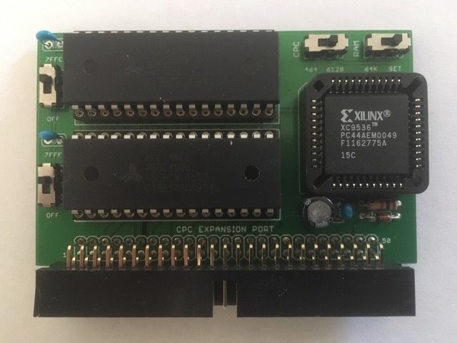
The Z-Mem manages all PAL modes for the 464/664 and 464+ users. A switch "RAM 64K/SET" let you run like a basic 6128 ou to state the quantity of memory to use up to 1024 Kb. The Z-MEM will be sold for 29.90 € for 2x512K SRAM (other configurations to be defined later).
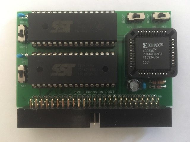
The D-ROM (dual rom) is a 2x 256Kb flash board for 19.90 €) that allows you to handle two independants sets of ROM, boot, firmware or DOS (ROM7 compatible). The principle is the same than the ROM part of the X-Mem. The card let you boot on either of them with its own firmware and basic. A switch "ROM7 YES/NO" let users with CPC without AMSDOS (or which cant be desactivated) to install their own DOS.
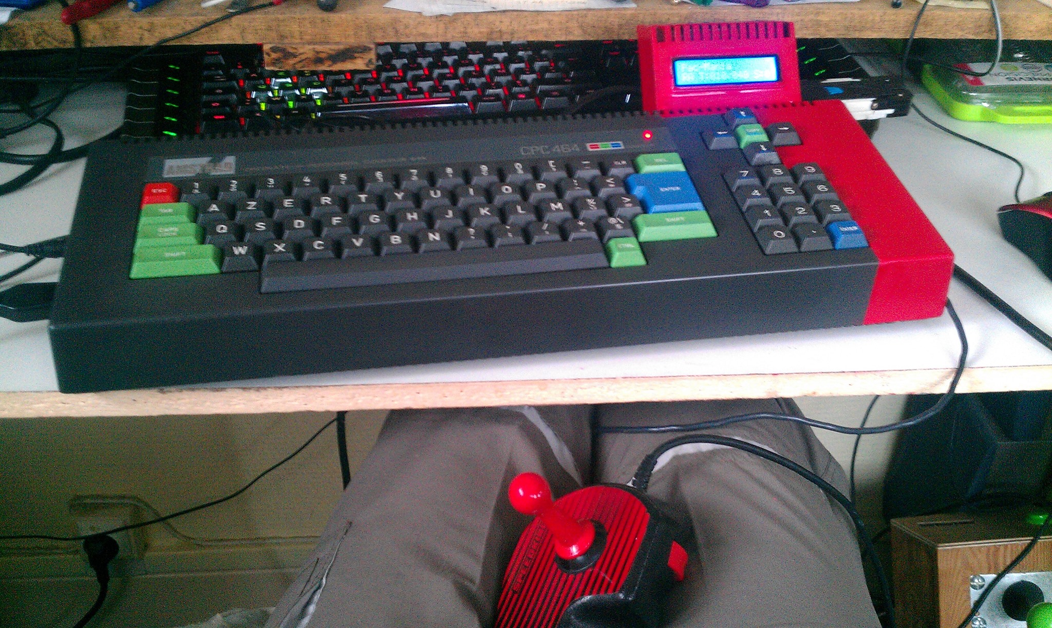
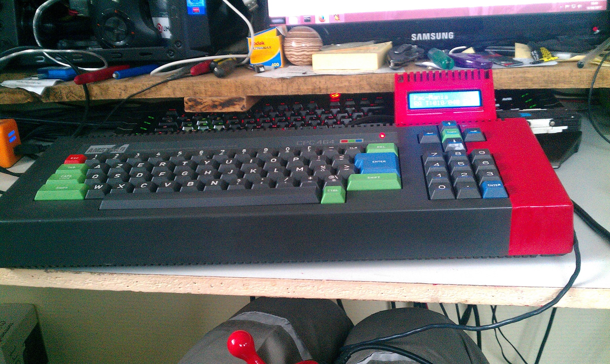
Here are the last 3 photos byOlivier Bruneau who had an Amstrad CPC 464 with a defective drive tape, so he removed it after seing a forum where someone had the same problem and the radical solution he used. The photos now includes a DDI3 USB Floppy Emulator by Zaxon.
Thanks to Olivier for letting me put his photo on the web site.
SymbOS v3 by Prodatron, the Amstrad CPC multitasking operating system can be downloaded now. It also exists for Amstrad PCW, MSX and now for Elan enterprise, with support of network which appeared in the beta of june 2016.
There is now an updated documentation in english of Symbos 3.
Release 3.0 [30.08.2017]
Network enabled
- Network daemon: The new Network Daemon application enables SymbOS for full TCP/IP based network and internet access includung multiple connections for multiple applications at the same time. Both TCP and UDP protocols within the transportation layer are supported as well as services like DHCP and DNS. The Network Daemon runs as a background service and can be used by any application via its network API.
- Supported network hardware: SymbOS supports the DenYoNet (MSX), the GR8NET (MSX) and the M4Board (CPC) hardware expansions for internet access via ethernet or wifi.
- Local host: A special local host version of the Network Daemon makes it possible to run all network apps even on machines without additional network hardware.
- Tools and games: Standard tools like WGET, NSLOOKUP and NETSTAT have been developed as well as more complex applications like syMIRC and TELNET and even network games (see "new applications on the Symbos website").
Enterprise port
- 4th supported Z80 platform: SymbOS has been fully ported to the Enterprise 64/128 machines as well. After the Amstrad CPC, the MSX and the PCW Joyce it's the fourth supported Z80 platform now.
- FDC and SD card support: SymbOS EP contains a driver for the standard EXDOS WD1772 based floppy disc controller as well as for the "SD adapter premium" by Szergej Butov.
- Standard screen resolutions: SymbOS currently supports CPC-like screen resolutions of 320x200 (4 colours) and 640x200 (2 colours).
- Taskbar with own colours: Due to the capabilities of the Nick video chip the task bar can have its own separated 4 colours.
- EnterMice and BoxSoft mouse support: Beside via keyboard and joystick it is also possible to control the mouse pointer with the BoxSoft interface as well as with the new EnterMice hardware, which allows to connect a proportional PS/2 mouse to the Enterprise.
- 1MB support: SymbOS EP supports up to 1024KB of RAM. As a special feature of the EP version it also handles fragmented memory banks within the 4MB address space.
- Adapted sound apps: SymAmp (by Geco) and Speech (by Gflorez) have been ported to the Enterprise "Dave" music chip; it's not AY compatible but it is able to emulate it in a good way.
MSX 1 support
- MSX1 with V9990: SymbOS MSX is now running on MSX1 machines with an attached Graphics9000 or Powergraph graphic card (V9990), too. Of course enough RAM (128KB) and a mass storage device is required as usual.
Extended Desktop
- Desktop replacement: The extension module, which could already be optionally loaded since SymbOS 1.1 on machines with memory expansions, now includes the "Extended Desktop" which now behaves more or less like the desktop of Windows 98.
- Advanced icon handling: The Extended Desktop supports any amount of 4 and 16 colour desktop icons. Icons can be added (right click an empty area), renamed ("slow" double click an icon) and changed (right click the icon) directly inside the desktop via intuitive dialogues. Icons can be lined up, auto arranged, copied, pasted and deleted directly.
- Nested startmenu entries: There is no real limit for startmenu entries anymore, too. Nested submenus are possible as well as any name and path lengths. Beside inside the "program" menu you can also add new entries and submenus on top of the start menu. The new startmenu editor application is part of the control panel.
- Autostart menu: Beside the existing autostart option (control panel -> system -> autostart) you can also add as many entries as needed to the "Autostart" folder of the startmenu. All these entries will be automatically executed after booting.
- Desktop widgets: Widgets are little applications, which are integrated directly inside the desktop without having own forms. They are working like typical widgets known from existing desktop GUIs and smartphones (clock, weather, CPU meter etc.). They can be freely placed inside the desktop area and usually resized as well.
Operating system (general)
- Help browser: The new help browser allows displaying and browsing through HLP files, which will be included now in many applications. Documents may contain nested chapters, links and different font types. The search function returns a complete result list.
- Micro kernel: Process priorities can be changed during runtime; new slot/subslot switching function available for MSX hardware drivers.
- Browse dialogue: File extensions will be added automatically when typing in filenames without a dot at the end. E.g. if you save a new textfile in Notepad and you don't specify an extension, ".TXT" will be added.
- Keyboard presets: The control panel allows loading and saving of whole keyboard definitions (region and/or machine specific) in special "*.KYB" files.
Desktop Manager
- Colour schemes: For a uniform look of the GUI the user can define a colour scheme, so that all apps appear in the same coloured way.
- Full 16 colour support completed: All remaining GUI elements and form controls have been extended with 16 colour support, either directly of by using the user defined colour scheme.
- Systray icons: The systray area of the taskbar can now been used by applications for adding and removing their own clickable systray-icons.
- Context menus: This new feature introduces context menus, which can appear at any place within an application (e.g. on right-click).
- 16 colour icons: Apps may contain an additional 16 colour version of their icons, which will be used for the desktop links of the "Extended Desktop".
Additional supported hardware
- GR8NET SD card reader: With the network and SD card driver the important parts of one of the most powerful MSX hardware of the last time are supported in SymbOS.
- M4Board SD card reader: The M4 makes it possible: First time, that you can access FAT32 32GB SD cards on the CPC in SymbOS directly in "highspeed mode".
- HxC direct SD card access: SymbOS CPC supports the direct mode of the HxC floppy emulator as well. Using the internal FDC765 as a mass storage interface is slow, but you are still able to access very big files from a FAT32 32GB SD card - for the first time on a CPC.
- Albireo USB mouse: The Albireo interface makes it possible to connect real proportional USB mouses to the CPC - and yes, again for the first time! SymbOS supports up to 3 buttons and the wheel. Gaming mouses may not work due to their enhanced USB protocol.
- Rookie drive USB mouse: Nearly the same interface is available for the MSX: Beside other USB hardware the Rookie drive allows to connect real proportional mouses to the MSX in the same way.
- MultiPlay Amiga mouse: You can connect original Amiga mouses to the CPC with the MultiPlay interface and use them for SymbOS.
- Dobbertin Smart Watch: Beside the SYMBiFACE II RTC SymbOS now also supports the Dobbertin Smart Watch (real time clock) and its new clone. Together with the already mentioned new hardware it's now possible to replace the whole SYMBiFACE II hardware expansion - ops yes, for the first time - after 10 years 
- SE-ONE radio: Now you can listen to any available FM radio station with SymbOS MSX, using the SE-ONE and the new Radio application.
SymShell 2.0
- TAB autocomplete: just type the first few letters of a filename or directory and SymShell will find the full name after pressing TAB multiple times; this is working for any nested subdirectory as well.
- advanced COPY command: supports filemasks and complex path statements, uses up to 64K copy buffer and is able to copy multiple files into one destination file.
- multiple file handling: for REN, MOVE and TYPE
- new DATE/TIME commands: for reading and setting the actual time and date.
- new ATTRIB command:: for editing all attributes of existing files.
- file attribution flags: New options for all multiple file commands (COPY, REN, MOVE, TYPE, ATTRIB)
- extended HELP command: SymShell includes a new help system based on a central "MAN" file. Type HELP for any details.
- Path function: SymShell apps can use a special path function for merging user-typed pathes with the actual one.
- System path: If not present in the actual folder the system will search for COM files in the system path as well and execute them there if found.
New applications
- UnZip: ZIP/GZ archive uncompressor; the first Unzip implementation for Amstrad CPC, PCW and Enterprise in history thanks to the Gunzip MSX project
- SymTel: Telnet client with ANSI, VT100 and VT52 terminal support
- syMIRC: IRC client with multiple channel support (by EdoZ, using Quigs)
- Wget: HTTP file download utility
- Symple Messenger: proprietary internet messenger (by Trebmint & EdoZ, using Quigs)
- Columns: Puzzle game (by EdoZ, using Quigs)
- Battleship: this classical battle ship implementation is the first SymbOS network game ever (by EdoZ, using Quigs)
- Snake: classic snake implementation; the first realtime multiplayer network game for SymbOS (by EdoZ, using Quigs)
- Picture-Slider: classical puzzle game (by Trebmint, using Quigs); the first Quigs game which has ever been started many years ago
- FM Radio: search for available FM radio stations and listen to them in SymbOS MSX (by EdoZ, using Quigs)
- Performance monitor: system performance measurement (by EdoZ, using Quigs)
- SymBUS: remote control utility (by EdoZ, using Quigs)
- DiMon: simple sector dump utility
- Ahead: batch utility for adding and removing AMSDOS binary fileheaders in multiple files
- Network tools: NsLookup, Netstat
- Desktop widgets: Clock, CPU Meter
- Little demos: Bubble and Flying SymbOS demo animations (by EdoZ, using Quigs)
Miscellaneous
- New professional SymbOS manual: The new SymbOS manual is designed and written by EdoZ and is available as a full-featured english PDF document. With a lot of pictures and screenshots this documentation makes it really easy to get started with SymbOS and its applications on any supported Z80 platform.
- Upgraded website: The website has been extended with a new application area. Beeing database generated it's now always up-to-date and more detailed. A new area about the supported platforms and supported hardware expansions have been added to the website as well.
- Files renamed: For an improved readability filenames of existing apps as well as of system files have been renamed, the old "app*.exe" and "cmd*.com" schematic isn't used anymore.
- Bug fixing: Bugs have been removed as usual, including some very very old ones (e.g. releasing clusters in the AMSDOS filesystem driver).
For more news, Go to home page